


FR200P 07SZ1-R (PH60) (CU/SR/LSZH 450/750V Class 2)
| Application: |
The cables are designed, manufactured and tested for general application in power supply and signal wiring, for emergency circuit and fire circuit control. |
| STANDARDS: |
Basic design to BS 7629-1 |
FIRE PERFORMANCE
|
Circuit Integrity |
IEC 60331-21; BS 6387 CWZ; DIN VDE 0472-814(FE180); BS 8434-1 (30mins); BS 5839-1 Clause 26 2d; CEI 20-36/2-1; SS229-1; NBN C 30-004 (cat. F3); NF C32-070-2.3(CR1) |
|
Circuit Integrity with mechanical shock |
EN 50200(PH60); CEI 20-36/4-0 |
|
Circuit Integrity with mechanical shock & water spray |
EN 50200 annex E |
|
System circuit integrity |
DIN 4102-12, E30 depending on lay system |
|
Flame Retardance (Single Vertical Wire Test) |
EN 60332-1-2; IEC 60332-1-2; BS EN 60332-1-2; VDE 0482-332-1 ; NBN C 30-004 (cat. F1); NF C32-070-2.1(C2); CEI 20-35/1-2; EN 50265-2-1*; DIN VDE 0482-265-2-1* |
|
Reduced Fire Propagation (Vertically-mounted bundled wires & cable test) |
EN 60332-3-24 (cat. C); IEC 60332-3-24; BS EN 60332-3-24; VDE 0482-332-3; NBN C 30-004 (cat. F2); NF C32-070-2.2(C1); CEI 20-22/3-4; EN 50266-2-4*; DIN VDE 0482-266-2-4 |
|
Halogen Free |
IEC 60754-1; EN 50267-2-1; DIN VDE 0482-267-2-1; CEI 20-37/2-1 ; BS 6425-1* |
|
No Corrosive Gas Emission |
IEC 60754-2; EN 50267-2-2; DIN VDE 0482-267-2-2; CEI 20-37/2-2 ; BS 6425-2* |
|
Minimum Smoke Emission |
IEC 61034-1&2; EN 61034 -1&2; DIN VDE 0482-1034-1&2; CEI 20-37/3-1&2; EN 50268-1&2*; BS 7622-1&2* |
|
No Toxic gases |
NES 02-713; NF C 20-454 |
Note: Asterisk * denotes superseded standard.
VOLTAGE RATING
450/750 V
CABLE CONSTRUCTION
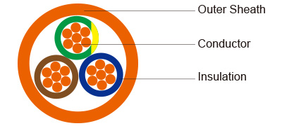
- Conductors: Plain annealed copper wire, stranded according to IEC(EN) 60228 class 2.
- Insulation: Fire resistant silicone rubber compound type EI2 as per BS 7655-1.1.
Cabling: The cores are cabled together in concentric layers with suitable non-hygroscopic fillers.
- Outer Sheath: Thermoplastic LSZH compound type LTS3 as per BS 7655-6.1 (Thermosetting LSZH
compound type SW2-SW4 as per BS 7655-2.6 can be offered.)
COLOUR CODE
Insulation Colour:
Without earth conductor
2 cores blue - brown
3 cores brown - black - grey
4 cores blue - brown - black - grey
5 cores blue - brown - black - grey - black
With earth conductor
3 cores yellow/green - blue - brown
4 cores yellow/green - brown - black - grey
5 cores yellow/green - blue - brown - black - grey
Sheath Colour: Colour red (other colours on request)
Physical AND THERMAL PROPERTIES
Temperature range during operation (fixed state): -30°C – +90°C
Temperature range during installation (mobile state): -20°C – +50°C
Minimum bending radius: 7.5 x Overall Diameter
Electrical PROPERTIES
|
Dielectric test: |
2500 V r.m.s. x 5' (core/core) |
|
Insulation resistance |
≥300 MΩ x km (at 20°C) |
|
Short circuit temperature |
350°C |
CONSTRUCTION PARAMETERS
|
Cable Code |
No. of Core X Cross Section |
Nominal Insulation Thickness |
Nominal Sheath Thickness |
Nominal Overall Diameter |
Approx. Weight |
|
|
mm2 |
mm |
mm |
mm |
kg/km |
|
2 core, |
|||||
|
FFX200 07SZ1-R (PH60) |
2x1.5 |
0.8 |
1.0 |
7,8 |
96 |
|
FFX200 07SZ1-R (PH60) |
2x2.5 |
0.9 |
1.1 |
9,2 |
138 |
|
FFX200 07SZ1-R (PH60) |
2x4.0 |
0.9 |
1.2 |
10,5 |
189 |
|
3 core |
|||||
|
FFX200 07SZ1-R (PH60) |
3x1.5 |
0.8 |
1.0 |
8,3 |
116 |
|
FFX200 07SZ1-R (PH60) |
3x2.5 |
0.9 |
1.1 |
9,8 |
169 |
|
FFX200 07SZ1-R (PH60) |
3x4.0 |
0.9 |
1.2 |
11,6 |
246 |
|
4 core |
|||||
|
FFX200 07SZ1-R (PH60) |
4x1.5 |
0.8 |
1.1 |
9,3 |
147 |
|
FFX200 07SZ1-R (PH60) |
4x2.5 |
0.9 |
1.2 |
11,3 |
222 |
|
FFX200 07SZ1-R (PH60) |
4x4.0 |
0.9 |
1.3 |
12,5 |
299 |
|
5 core |
|||||
|
FFX200 07SZ1-R (PH60) |
5x1.5 |
0.8 |
1.1 |
10,5 |
180 |
|
FFX200 07SZ1-R (PH60) |
5x2.5 |
0.9 |
1.2 |
12,3 |
259 |
|
FFX200 07SZ1-R (PH60) |
5x4.0 |
0.9 |
1.3 |
14,0 |
359 |
Electrical PROPERTIES
Conductor Operating Temperature : 90°C
Ambient Temperature : 30°C
Current-Carrying Capacities (Amp)
|
Nominal Cross Section Area |
Reference Method 4 (enclosed in an conduit insulated wall etc) |
Reference Method 3 (enclosed in conduit on a wall or ceiling, or in trunking) |
Reference Method 1 (clipped direct) |
Reference Method 11 (on a perforated cable tray), or Reference Method |
|||
|
one 3-core cable or one 4-core cable 3-phase a.c. |
one 2-core cable single phase a.c. or d.c. |
one 3-core cable or one 4-core cable 3-phase a.c. |
one 2-core cable singlephase a.c. or d.c. |
one 3-core cable or one 4-core cable 3-phase a.c. |
one 2-core cable singlephase a.c. or d.c. |
one 3-core cable or one 4-core cable 3-phase a.c. |
|
|
1 |
2 |
3 |
4 |
5 |
6 |
7 |
8 |
|
mm2 |
A |
A |
A |
A |
A |
A |
A |
|
1.5 |
16.5 |
22 |
19.5 |
24 |
22 |
26 |
23 |
|
2.5 |
22 |
30 |
26 |
33 |
30 |
36 |
32 |
|
4 |
30 |
40 |
35 |
45 |
40 |
49 |
42 |
Voltage Drop (Per Amp Per Meter)
|
Nominal Cross Section Area |
2-core cable d.c. |
2-core cable single- phase a.c |
3-core or 4-core cable 3-phase a.c. |
|
1 |
2 |
3 |
4 |
|
mm2 |
mV/A/m |
mV/A/m |
mV/A/m |
|
1.5 |
31 |
31 |
27 |
|
2.5 |
19 |
19 |
16 |
|
4 |
12 |
12 |
10 |