


| Applications : | These cables are flame retardant, low smoke, halogen free and mud resistant, used for fixed installation for medium voltage power. |
| Standards : | IEC 60092-353; IEC 60092-351; IEC 60092-359; IEC 60332-1; IEC 60332-3-22; IEC 60754-1,2; IEC 61034-1,2; NEK 606:2004 |
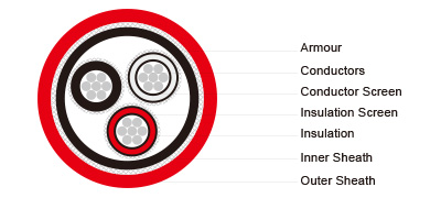
| Conductors : | Circular tinned annealed stranded copper to IEC 60228 class 2. |
| Conductor Screen : | Semi conducting material. |
| Insulation : | Halogen-free EPR. XLPE can be offered as an option (for TFOU cable). |
| Insulation Screen : | Semi conducting material and tinned copper wire braid. |
| Bedding : | Halogen free compound. |
| Armour : | Tinned copper wire braid. |
| Outer Sheath : | Halogen free thermosetting compound, SHF2 (for TYPE P2), or halogen free mud resistant thermosetting compound, SHF MUD (for TYPE P2/P9),coloured red. |
Electrical Characteristics :
|
Nominal Cross Section Area |
mm² |
16 |
25 |
35 |
50 |
70 |
95 |
120 |
|
Nominal Conductor Diameter |
mm |
5.1 |
6.5 |
7.4 |
8.7 |
10.3 |
12.2 |
13.8 |
|
Maximum DC Resistant@20℃ |
Ω/km |
1.16 |
0.734 |
0.529 |
0.391 |
0.27 |
0.195 |
0.154 |
|
Continuous Current Rating@45℃1 Core |
A |
96 |
127 |
157 |
196 |
242 |
293 |
339 |
|
Continuous Current Rating@45℃3 Core |
A |
67 |
89 |
110 |
137 |
169 |
205 |
237 |
|
Short Circuit Current 1s |
A |
2290 |
3580 |
5010 |
7150 |
10020 |
13590 |
17170 |
|
Operating Voltage |
KV |
3.6/6 |
3.6/6 |
3.6/6 |
3.6/6 |
3.6/6 |
3.6/6 |
3.6/6 |
|
Nominal Cross Section Area |
mm² |
150 |
185 |
240 |
300 |
400 |
500 |
630 |
|
Nominal Conductor Diameter |
mm |
15.1 |
17.0 |
19.6 |
21.9 |
24.6 |
27.6 |
32.5 |
|
Maximum DC Resistant@20℃ |
Ω/km |
0.126 |
0.1 |
0.0762 |
0.0607 |
0.0475 |
0.0369 |
0.0286 |
|
Continuous Current Rating@45℃1 Core |
A |
389 |
444 |
522 |
601 |
690 |
780 |
890 |
|
Continuous Current Rating@45℃3 Core |
A |
272 |
311 |
365 |
421 |
483 |
546 |
623 |
|
Short Circuit Current 1s |
A |
21460 |
26470 |
34340 |
42930 |
57230 |
71540 |
90140 |
|
Operating Voltage |
KV |
3.6/6 |
3.6/6 |
3.6/6 |
3.6/6 |
3.6/6 |
3.6/6 |
3.6/6 |
Ambient Temperature Correction Factors :
|
Ambient Temperature Correction Factors |
35 |
40 |
45 |
50 |
55 |
60 |
65 |
70 |
75 |
80 |
|
Rating Factor |
1.1 |
1.05 |
1.0 |
0.94 |
0.88 |
0.82 |
0.74 |
0.67 |
0.58 |
0.47 |
Mechanical and Thermal Properties :
Bending Radius :15×OD (during installation); 9×OD (fixed installed).
Temperature Range : -20℃ ~ +90℃.
Dimensions and Weight :
|
Construction No. of cores×Cross section (mm²) |
Nominal Insulation Thickness mm |
Nominal Sheath Thickness mm |
Nominal Overall Diameter mm |
Nominal Weight kg/km |
|
|
Inner |
Outer |
||||
|
1×16 |
2.5 |
1.4 |
1.1 |
22.8 |
780 |
|
1×25 |
2.5 |
1.5 |
1.1 |
24.0 |
1020 |
|
1×35 |
2.5 |
1.5 |
1.2 |
25.1 |
1155 |
|
1×50 |
2.5 |
1.6 |
1.2 |
26.3 |
1320 |
|
1×70 |
2.5 |
1.6 |
1.3 |
28.2 |
1595 |
|
1×95 |
2.5 |
1.7 |
1.3 |
30.0 |
1905 |
|
1×120 |
2.5 |
1.8 |
1.4 |
31.8 |
2235 |
|
1×150 |
2.5 |
1.8 |
1.4 |
33.5 |
2550 |
|
1×185 |
2.5 |
1.9 |
1.5 |
35.4 |
3015 |
|
1×240 |
2.6 |
2.0 |
1.5 |
38.8 |
3725 |
|
1×300 |
2.8 |
2.1 |
1.6 |
42.3 |
4625 |
|
1×400 |
3.0 |
2.2 |
1.7 |
46.6 |
5420 |
|
1×500 |
3.2 |
2.4 |
1.8 |
50.8 |
6610 |
|
1×630 |
3.2 |
2.5 |
1.9 |
55.1 |
8170 |
|
3×16 |
2.5 |
2.2 |
1.6 |
44.9 |
2930 |
|
3×25 |
2.5 |
2.3 |
1.7 |
45.4 |
3390 |
|
3×35 |
2.5 |
2.4 |
1.8 |
47.6 |
3820 |
|
3×50 |
2.5 |
2.5 |
1.9 |
50.9 |
4495 |
|
3×70 |
2.5 |
2.7 |
2.0 |
54.8 |
5585 |
|
3×95 |
2.5 |
2.8 |
2.1 |
58.9 |
6765 |
|
3×120 |
2.5 |
3.0 |
2.2 |
63.5 |
8165 |
|
3×150 |
2.5 |
3.1 |
2.3 |
67.4 |
9495 |
|
3×185 |
2.5 |
3.3 |
2.4 |
75.8 |
10660 |
|
3×240 |
2.6 |
3.5 |
2.5 |
82.3 |
11660 |
|
3×300 |
2.8 |
3.8 |
2.7 |
89.3 |
12940 |